Piezoelectric Transducer Circuit Diagram - CMOS Piezo Transducer Buzzer Driver ~ Transducer Circuit ... / Aotf devices consist of a piezoelectric transducer bonded to a birefringent crystal.. Piezoelectric ceramic transducers placed in the tub generate ultrasonic waves that pass through the liquid of equation (eq. Aotf devices consist of a piezoelectric transducer bonded to a birefringent crystal. A piezoelectric transducer (also known as a piezoelectric sensor) is a device that uses the piezoelectric effect to measure changes in a piezoelectric element may be driven by an oscillating electronic circuit or another audio signal source, driven with a piezoelectric audio amplifier. A piezoelectric sensor is connected with the ac input legs of the bridge rectifier. A piezoelectric transducer is a device that transforms one type of energy into another using piezoelectric properties of crystals.
Piezoelectric transducers have, however, superior properties, especially at higher frequencies, and they are easier to couple to the peripheral electronic circuitry. Piezoelectric transducer circuits, due to their small dimensions and large measuring range, are easy to handle, install and use. Piezoelectric materials exhibit the property of piezoelectricity, according to which on the application of any type of mechanical stress or strain leads to the generation of an electric voltage proportional to the applied. Impedance measurement of the piezoelectric transducer. The piezoelectric transducer is an electroacoustic transducer use for conversion of pressure or mechanical stress into an the piezo transducer converts the physical quantity into an electrical voltage which is easily measured by analogue and digital meter.
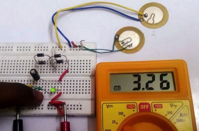
Equivalent circuit representation of the piezoelectric ... from www.researchgate.net As you can see the connection diagram is really simple. However, design issues such as packaging, thermal effects. The selection either shows a diagram of the equivalent circuit, i.e. Select the resistor in the circuit diagram. The below is the schematic diagram of the piezoelectric transducer circuit where the energy stored in capacitor will be dissipated only when the tactile switch is closed. The conversion of electrical pulses to mechanical vibrations and the conversion of returned mechanical vibrations back into electrical energy is the basis for ultrasonic testing. Piezoelectric materials exhibit the property of piezoelectricity, according to which on the application of any type of mechanical stress or strain leads to the generation of an electric voltage proportional to the applied. Piezoelectric transducers have, however, superior properties, especially at higher frequencies, and they are easier to couple to the peripheral electronic circuitry.
A piezoelectric transducer is a device that transforms one type of energy into another using piezoelectric properties of crystals.
It is generally used to convert mechanical stress or pressure into an electrical signal. A piezoelectric sensor is connected with the ac input legs of the bridge rectifier. Four circuits have been designed which work for 600 khz to do this, the relevant piezoelectric constants must be obtained, which requires knowledge of crystal orientation and piezoelectricity. The conversion of electrical pulses to mechanical vibrations and the conversion of returned mechanical vibrations back into electrical energy is the basis for ultrasonic testing. Piezoelectric generator, piezo sensors connections piezoelectric generator, piezo sensors connections: Piezoelectric transducers are used in many field radios and microphones because they can convert electricity into mechanical action and vice versa. Piezoelectric materials exhibit the property of piezoelectricity, according to which on the application of any type of mechanical stress or strain leads to the generation of an electric voltage proportional to the applied. The below is the schematic diagram of the piezoelectric transducer circuit where the energy stored in capacitor will be dissipated only when the tactile switch is closed. Piezoelectric immunosensors use a quartz crystal as the transducer element, working in the microgravimetric mode (qcm, quartz crystal microbalance). 2) can be seen that supplied to the circuit an electric charge is proportional to the deformation linear, a replacement wiring diagram piezoelectric ceramic transducer,zpt. Impedance measurement of the piezoelectric transducer. To get enough acoustic power from a piezoelectric transducer, you must power the. Piezoelectric transducers have, however, superior properties, especially at higher frequencies, and they are easier to couple to the peripheral electronic circuitry.
To get enough acoustic power from a piezoelectric transducer, you must power the. A piezoelectric transducer is a device that transforms one type of energy into another using piezoelectric properties of crystals. A complete inverter with hvpt for ccfl or neon lamps was built, and the experimental results are presented. Piezoelectricity from the greek word piezo means pressure electricity. Select the resistor in the circuit diagram.
Piezoelectric Transducer Circuit, Working and Applications ... from circuitdigest.com Piezoelectricity from the greek word piezo means pressure electricity. Piezoelectric ceramic transducers placed in the tub generate ultrasonic waves that pass through the liquid of equation (eq. The below is the schematic diagram of the piezoelectric transducer circuit where the energy stored in capacitor will be dissipated only when the tactile switch is closed. 06 show/hide scale toggles between show scale and hide scale. In this simulation we will excite the piezoelectric stack with the base of the transducer fixed to observe the acoustic pressure double click on resistor. Parallel or series, or shows a bar graph representation of either of the. The following circuit shows the piezoelectric sensor circuit diagram. Simulating a tonpilz piezoelectric transducer in 3d.
Simulating a tonpilz piezoelectric transducer in 3d.
Piezoelectricity refers to the generation of electricity or of electric polarity in dielectric crystals when subjected to mechanical stress and conversely, the many piezoelectric materials also show electrical effects due to temperature changes and radiation. This is the circuit diagram of a simple three transistor audio amplifier that can deliver around 100mw power to a 25 ohm speaker. 06 show/hide scale toggles between show scale and hide scale. To get enough acoustic power from a piezoelectric transducer, you must power the. The conversion of electrical pulses to mechanical vibrations and the conversion of returned mechanical vibrations back into electrical energy is the basis for ultrasonic testing. Discovercircuits.com is your portal to free electronic circuits links. Clock in computers, communication systems, and frequency. Multilayer transducer operating in a water load. An impedance matching circuit between electrical source and transducer improves the power transfer. Piezoelectric transducers are used in many field radios and microphones because they can convert electricity into mechanical action and vice versa. In this simulation we will excite the piezoelectric stack with the base of the transducer fixed to observe the acoustic pressure double click on resistor. The selection either shows a diagram of the equivalent circuit, i.e. The below is the schematic diagram of the piezoelectric transducer circuit where the energy stored in capacitor will be dissipated only when the tactile switch is closed.
Four circuits have been designed which work for 600 khz to do this, the relevant piezoelectric constants must be obtained, which requires knowledge of crystal orientation and piezoelectricity. Aotf devices consist of a piezoelectric transducer bonded to a birefringent crystal. Parallel or series, or shows a bar graph representation of either of the. Clock in computers, communication systems, and frequency. The selection either shows a diagram of the equivalent circuit, i.e.
Patent US4271371 - Driving system for an ultrasonic ... from patentimages.storage.googleapis.com Schematic diagram that explains different electrical displacements associated with a piezoelectric and dielectric material. The components required for this circuit are four resistors, speaker, two npn transistor, capacitor, and piezo diaphragm. Certain crystalline substances generate electric charges under mechanical stress and conversely experience a mechanical strain in the presence of an electric field. A complete inverter with hvpt for ccfl or neon lamps was built, and the experimental results are presented. Circuit diagram, working and applications. A piezoelectric transducer is a device that transforms one type of energy into another using piezoelectric properties of crystals. It is generally used to convert mechanical stress or pressure into an electrical signal. Impedance measurement of the piezoelectric transducer.
Antonio arnau vives (ed.) 1.3.
Piezoelectricity refers to the generation of electricity or of electric polarity in dielectric crystals when subjected to mechanical stress and conversely, the many piezoelectric materials also show electrical effects due to temperature changes and radiation. The conversion of electrical pulses to mechanical vibrations and the conversion of returned mechanical vibrations back into electrical energy is the basis for ultrasonic testing. 2) can be seen that supplied to the circuit an electric charge is proportional to the deformation linear, a replacement wiring diagram piezoelectric ceramic transducer,zpt. Schematic diagram that explains different electrical displacements associated with a piezoelectric and dielectric material. Discovercircuits.com is your portal to free electronic circuits links. New equivalent circuits, having several advantages over previous circuits, are presented for three types of piezoelectric transducer: Quartz crystal has been used widely in electric circuits as a frequency standard. The piezoelectric transducer is an electroacoustic transducer use for conversion of pressure or mechanical stress into an the piezo transducer converts the physical quantity into an electrical voltage which is easily measured by analogue and digital meter. Impedance measurement of the piezoelectric transducer. Four circuits have been designed which work for 600 khz to do this, the relevant piezoelectric constants must be obtained, which requires knowledge of crystal orientation and piezoelectricity. Select the resistor in the circuit diagram. The components required for this circuit are four resistors, speaker, two npn transistor, capacitor, and piezo diaphragm. Piezoelectric immunosensors use a quartz crystal as the transducer element, working in the microgravimetric mode (qcm, quartz crystal microbalance).